WEEK
FOUR
Embedded Programming
Task for this Week
Group Assignment
compare the performance and development workflows for other architecturesIndividual Assignment
browse through the data sheet for your microcontroller, write program for a microcontroller development board to interact (with local input &/or output) and communicate (remotely)Group Assignment
For the group Assignment we have to do comparision between two microcontroller. So we decided to compare the Arduino UNO board with Esp32 board.
Both this microcontroller are used to make many Iot projects. They are easy to use. Arduino and esp32 both are microcontroller board. Arduino
consist Atmega 328 p IC and Esp 32 board consist ESP32 chip. The Atmega 328p IC is consist 28 pins, in which only 17 Pins are used for Input and
output. While in Esp32 we have 25 input and output pin. The measure advantage of Esp32 is that it have inbuilt wifi and bluetooth ,while arduino
doesn't have. Arduino and Esp32 also have different memory configuration.
click here to read more about group assignment
Individual Assignment
Embedded System
This week is for emebedded programming. before doing something we have to know about what is embedded. Embedded means it consist many things in it.
So firstly let take a tour of embedded system. An embedded system is a system which consist Hardware, Software and operating system.
There is lots of advantages of Embedded system .
• Due to small size they use low power consumption
• Also they are low cost
• Durable with Higher speed working
Block diagram of Embedded system-
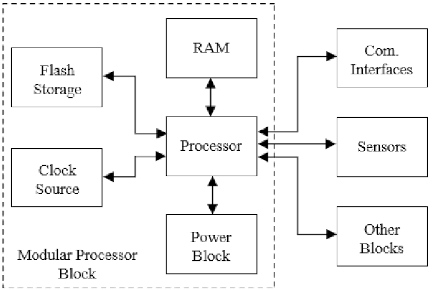
There main parameter of the embedded system is shown in the above block diagram.
• Processor
For the Human being the brain is main processor which control all the body part. Same thing is also applicable for the Embedded system.The processor which process all the activities and give transfer the data. It read the value given by sensors and other devices and give
to the other connected devices. The processor can perform multiple task, depends on its configuration. Generally in embeded system we use
microprecessor which required less power and small in size and perform the task better and faster.
• Power source
Power source is like a food for the embedded system. We provide the power externally , but if we look inside it, we see the power is suppliedevery part of embedded system. So power source manage the power consumption. It does not supply the power on those part which is inactive.
By performing this task they make able to embedded system to consume low power
• memory
This part Store the information For the embedded system. Memory also effect the performance of the system. they are SRAM, EPROM, Flash memory etc• Clock
The clock is also performed a major role in the embedded system. The clock is connect with processor which control the flow of data, Powertransmission and control the signal.
Reference
Microcontroller and microprocessor-
Microcontroller are the board which consist processor ,memory and input/output interface while a microprocessor is the processor only
Microcontroller are integrated cercuit or we can call them embeded system. The circuit of Microprocessor are hugeas compare to Microcontroller.
Microprocessor are use to perform multiple task while micro controller are used to perform repeatively task. We use microprocessor in our computer
and laptops. microcontrolller are used in fridge, Ac and other electronic device.
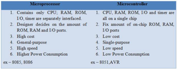
So for this reason we used microprocessor for multiple task and embedded system to perform a specific task.
ESP32s Board
I chose an ESP32s board as a embeded system and then start reading its datasheet. This board consist ESP32s chip in it. Many user made there ownboard by using this chip. This esp32s chip have inbuilt wifi and bluetoothLE (LE means Low Energy). By these it is different from another development
board like arduino. To know more about the esp32 I started read data sheet of it and I mentioned some details here.
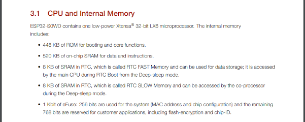
CPU and Memory
The below image shows the memory conficuration of the this board. it has 448 kb of read only memory (ROM) which is used to store the information.and cant be changed. 520kb of SRAM chip memory. More about the memory is given in the below picture
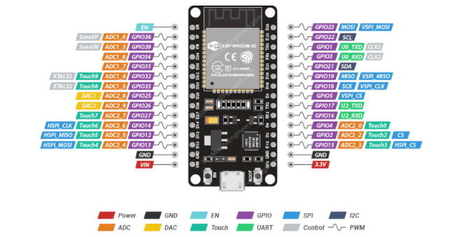
Pin Configuration of ESP32
• 34 Proframable GPIOs Pin-
This pin are general program input/output pins. and its number vary with vendors (esp32 has no specified board, we can make our own Esp32 boardby Using ESP32 chip)
• 18 12bit ADC channel-
This pins are used to convert analog into digital.• 2 pins for8bit DAC channel-
This pin are used to convert digital to analog.• 16 PWM Pins-
In digital pins we get data in the form of 0 and 1. but in PWM pin the signal varies between 0 and 254. if we want to glow a led at medium brightnesthis PWM pins help.
• 3 UART Interfaces-
In this pins we can connect the different devices which support Serial communication.• 3SPI interface-
These pins are used for serial programming.• 2 pins for I2c Interface-
I2C means Inter Integrated circuit. This pins provide serial communication between two device. We can connect two I2C interface device at a time.• 10 Capacitive touch sensor -
These pins act as touch sensor when we touch it. No need to connect external touch sensor.• 16 RTC GPIOs -
these pins are for RTC. which wake up and tell to sleep to CPU.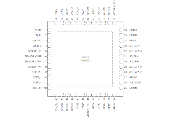
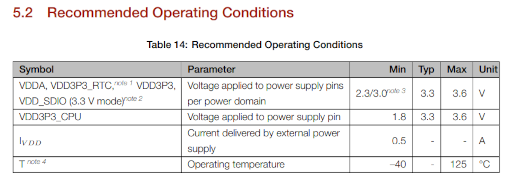
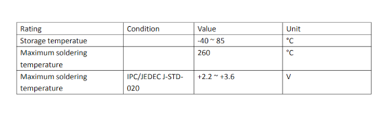
Power
The ESP32 chip required the voltage of 3.3V to operate. We provide 5V to the board. This board have voltage regulator which convert this powerchip requirement. Below Image are are contain parameter reagarding power consumption and operating condition.
Click here to read the data sheet of ESP32.
Arduino IDE
After reading all its technical data then I started to upload a programme in it. I used Arduino ide software for programming.This is a software used for the program the microcontroller like arduino ,esp32,esp8266 and many more. We can communicate with these board by
installing its library in it. In this software we used C++ and c language for the programming. So To Install this software go to "www.arduino.cc"
Then select software option and after that download the software as per your system specification. After download give permissions and install it.
Click here to download the software.
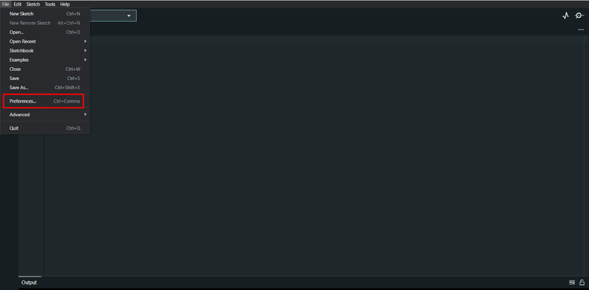
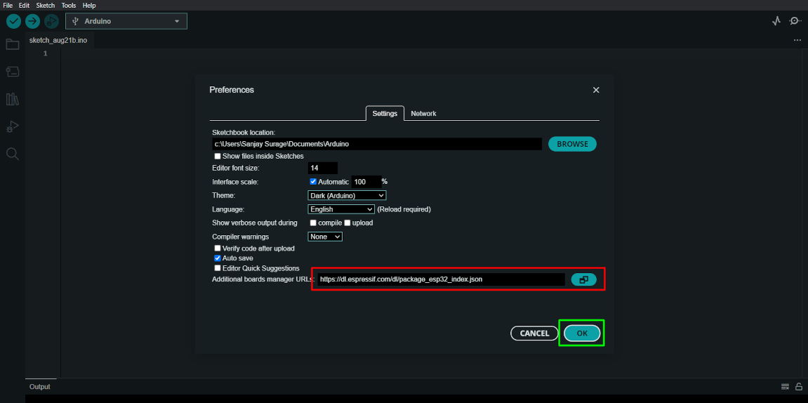
After installation, this Arduino Ide comminicate only with arduino. to communicate with esp32 we have to add esp32 url in preference section.
the url is given below "https://dl.espressif.com/dl/package_esp32_index.json"
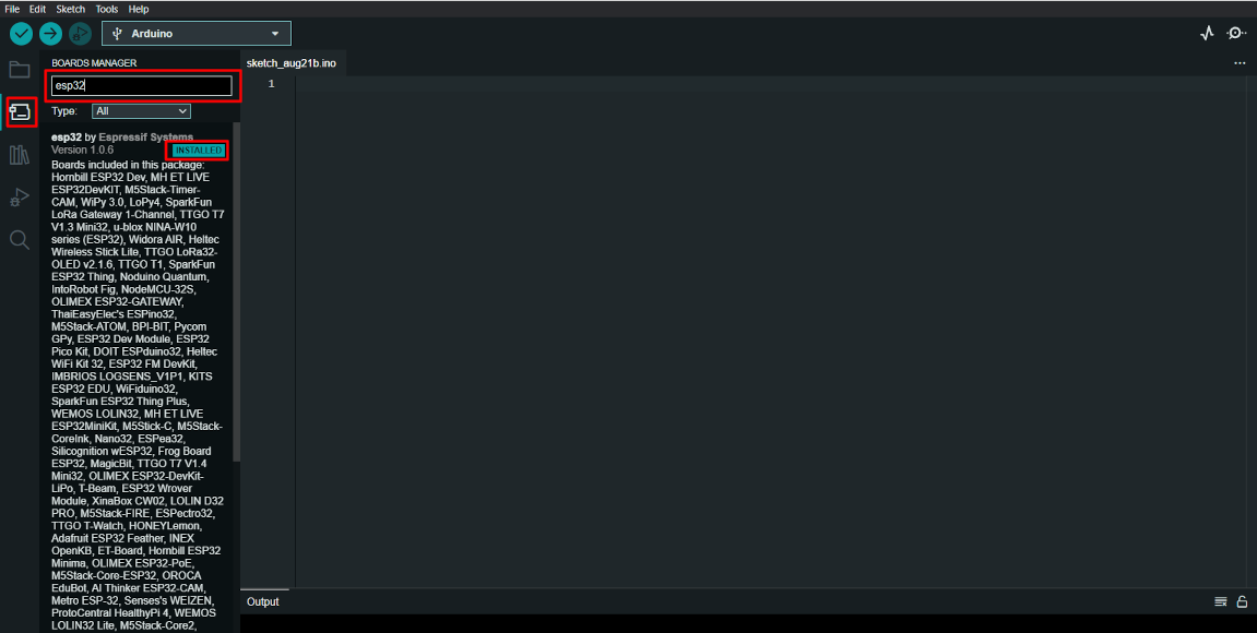
After this process we have to installed board manager library. Then go to the board manager and search ESP32 in it and Install the board manager
which in the below Image.
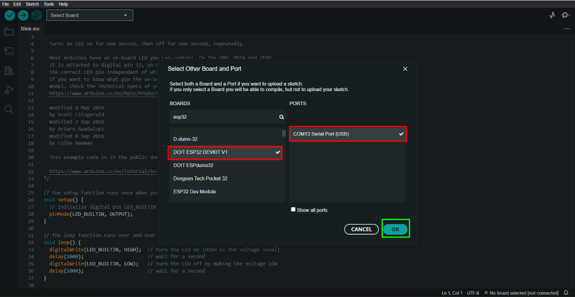
Now I write the code for blink the led. I defined the Led on Pin 2. After that we have to selct board and port. Port is way by which it communicate
with esp32 board. After selection we can see our board name and port at the right end corner.
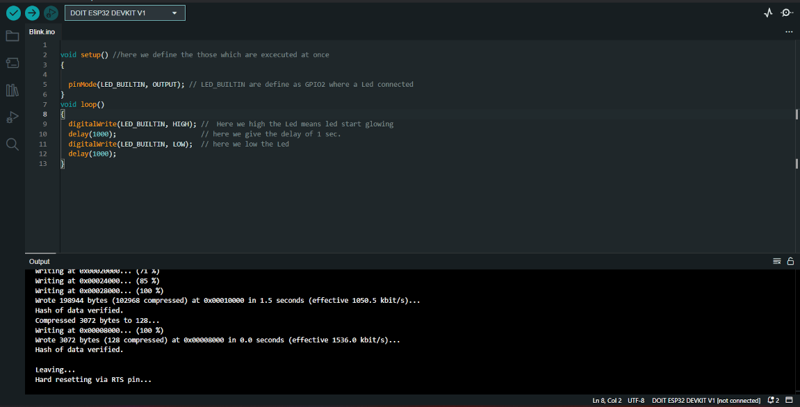
Now compile code. compiling means the software check the code and found error if any.after successfully compilation then Upload the program. I get a
trouble at the time uploading a program. After click upload button then at the downside it continously show connecting and not upladed.
so I searched about this problem on internet and found a solution. Solution is that we have to press Boot button atleast for three second and then
it uploaded successfully.
Code -
Result
LED control by Blynk
We know that the ESP32 have inbuilt wifi and bluetooth in it. So now I am going to use a webserver. For this I am goiing to use BlynkThis platform help us to read and control the data of our microcontroller. It uses a wifi by which we control the data transmission.
It also provide mobile applicaion for controlling microcontroller and IOT projects. So I start the process with blynk to control
the LED.
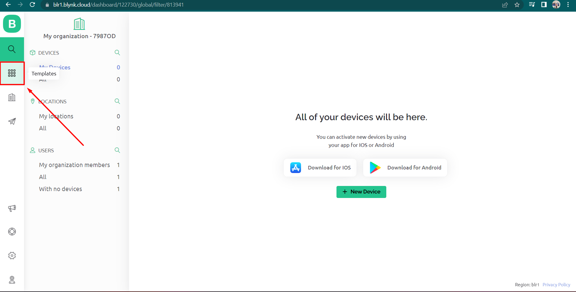
So first go to the BLYNK home page and then go to the login section. Login with you email-ID and then
a new window is appeare. So here I selected Tne template option.
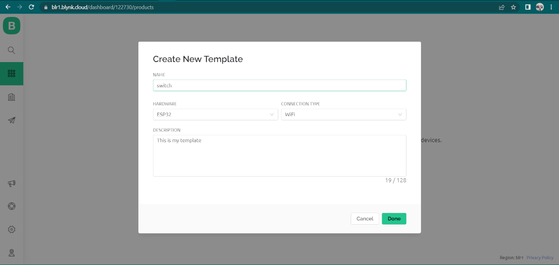
After that a window is open where we have add details. So I define the name of new template as "Switch". Then select ESP32 in hardware , select
in connection type and click on the done.
Now after that go to the "Datastream" Option and then select new datasteram and in this select the Digital option
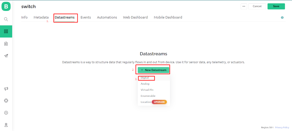
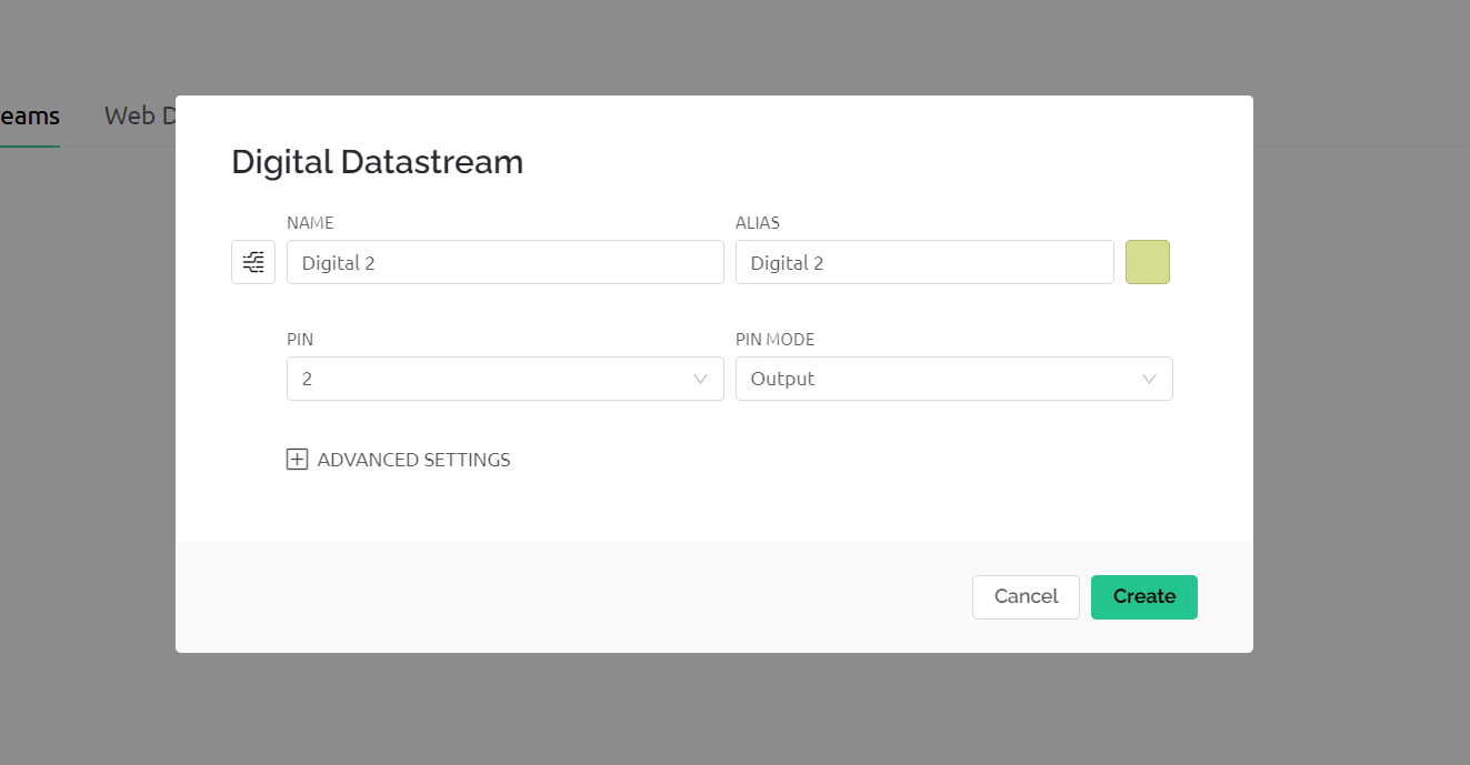
After that a new window apperaed where we have to add pin details of the led.
After That go to the web dashboard and select the widget for the switch.
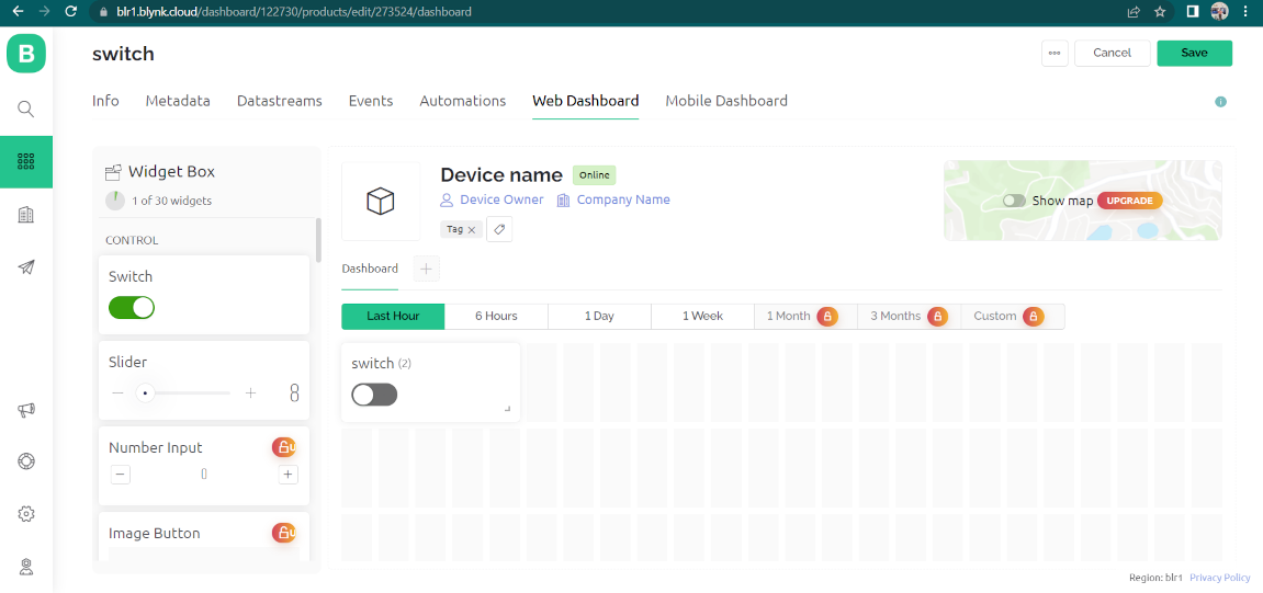
Now go the dashboard section and copy the ID which is created for our programming.
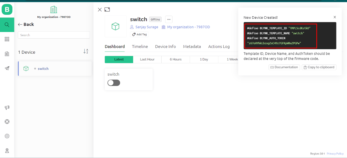 After That download the Library "BlynksimpleESP32" from library manager in arduino ide and Then Upload the following code. In this I paste the link
which I Copied from the Blynk webserver.
Code -
Result
Micropython with ESP32
In arduino Ide , we program the ESP32 with C++ language. Now we programme this microcontroller with micropython. Here we used the python
language for programming. This programming language generally used for the different web applications. To upload a code in Microcontroller by
using this language we have to install a software called "Thonny micropython"
To download this Software click here>
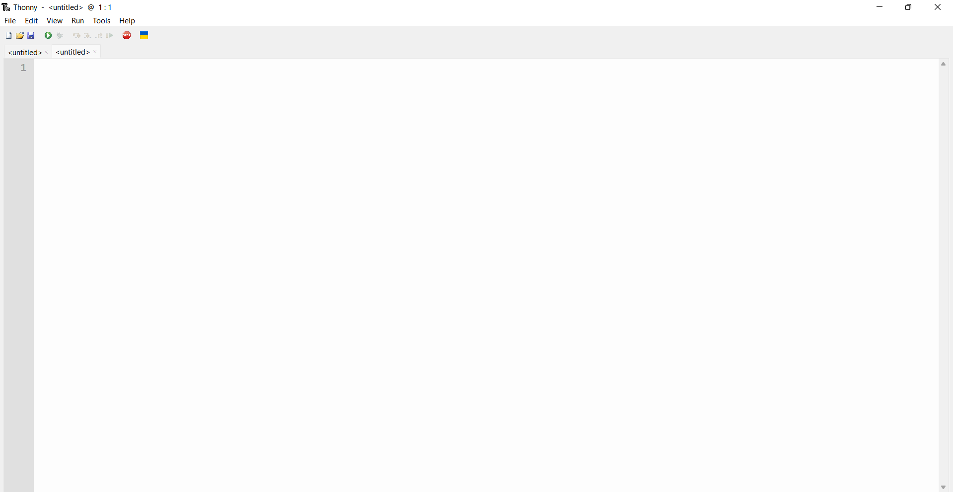
After the installation the window is appear like that.
In arduino Ide, when we add a new board, We paste the ".jason" link of that particular board in preference section. By which the arduino Ide
start communication with that board. Just like that, In this thonny microphthon we have to add the firmware of the board which we going to
use. By adding this firmware the micropython software start communication with that board. So I am decided to use the ESP32 board so I download
the firmware with micropython. To download the firmware-click here
After the download of firmware we have to install this firmware. So open the software and go to "Tool" option and select "Manage Plug ins"
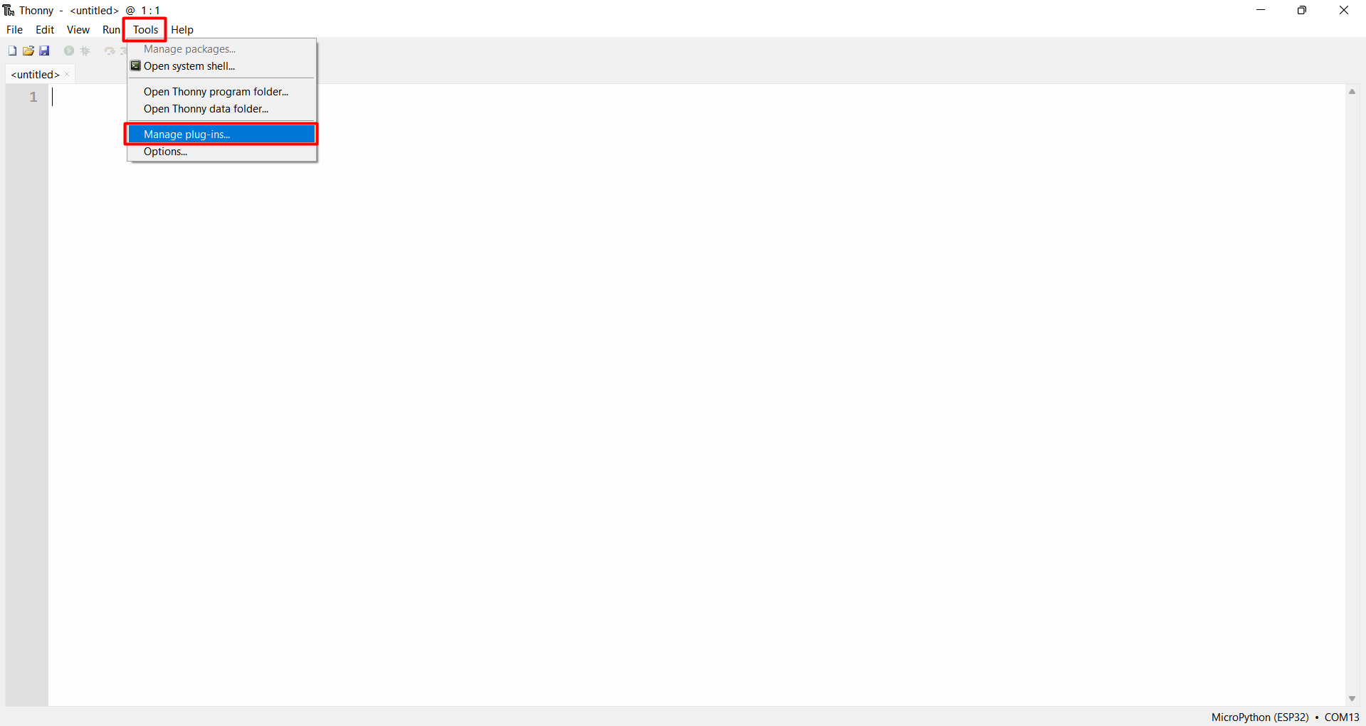
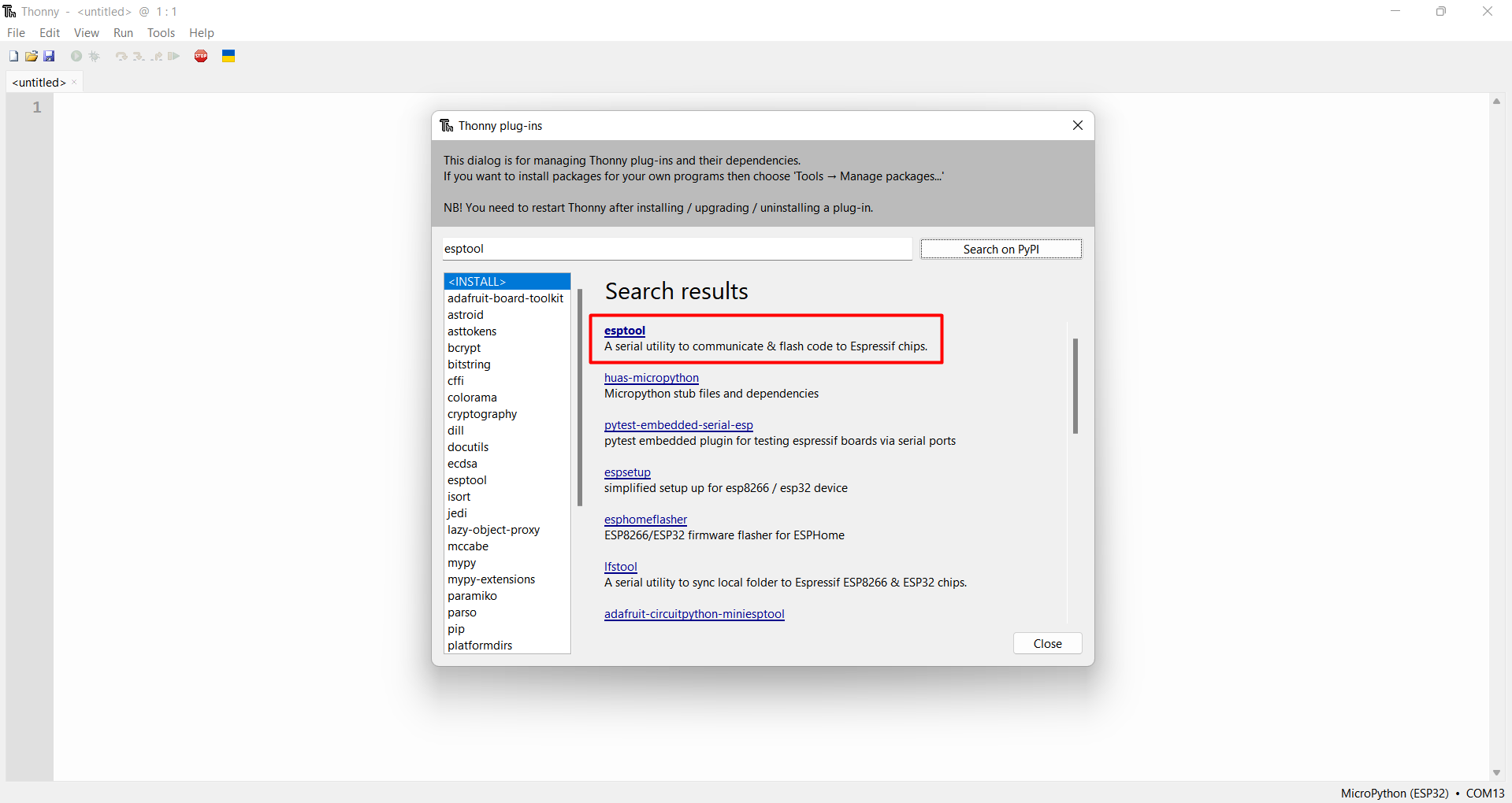
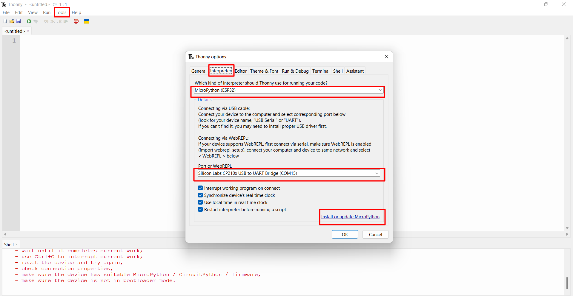
Then select "esptool" amd search it. After that install the first one result. After this select the "Tool" and then select "options" and then
select the Interpreter option. Now select the Micropython Esp32 and then select the port of your board and then select "Install or Update option"
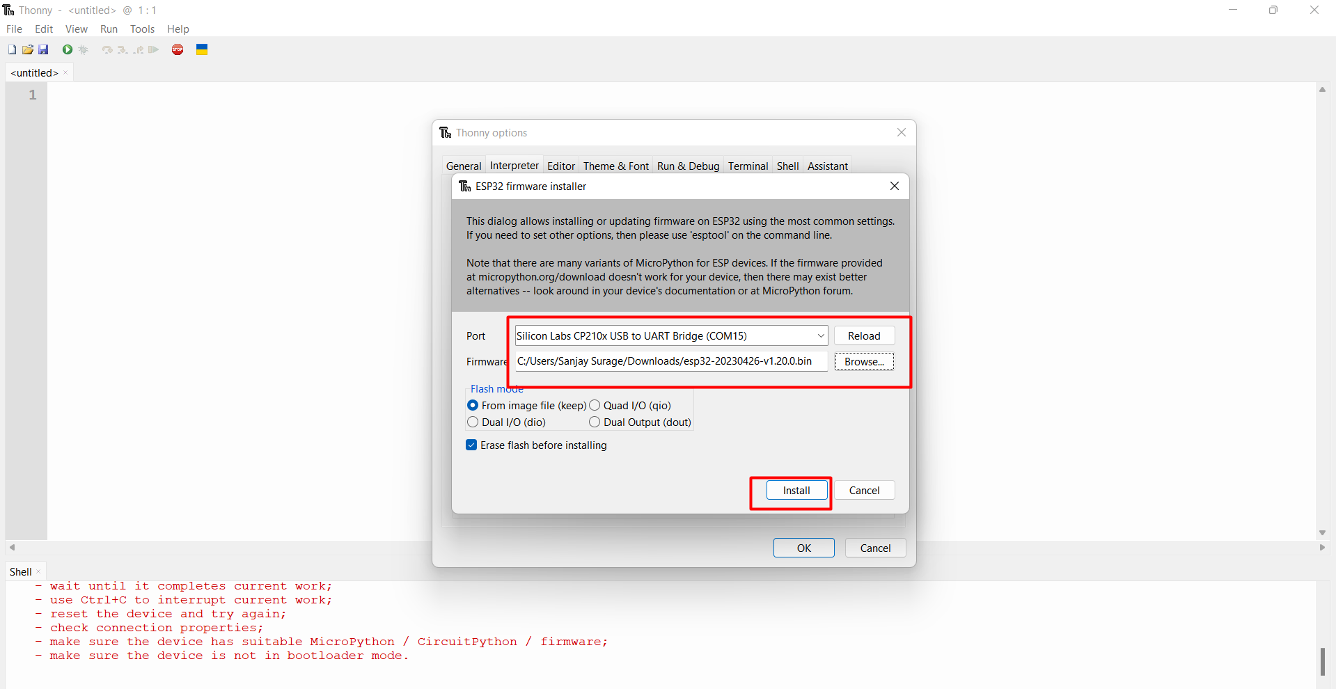
After that a new window appear. Here select the port and browse the firmware we downloaded and then click on install
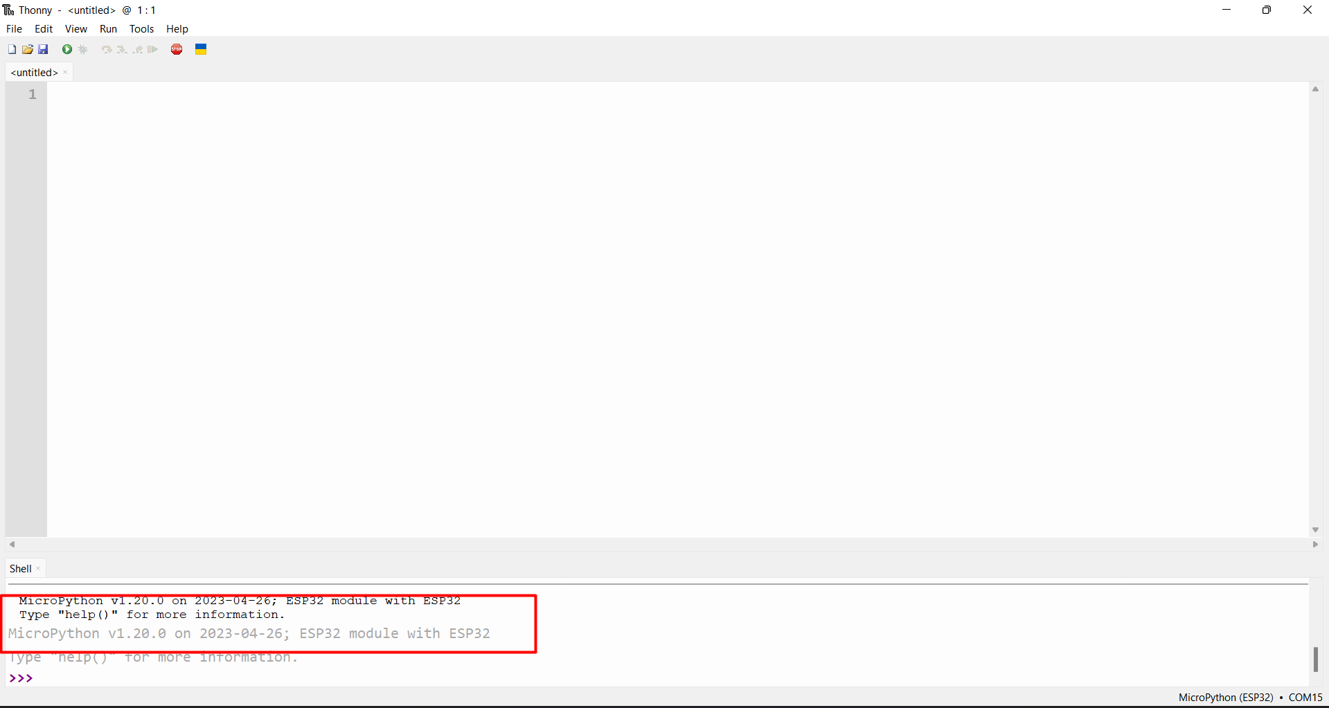
After the installation, our esp32 board succesfully connect to Thonny micropython.
I follow this "TUTORIAL" to install the Esp32 with micropython.
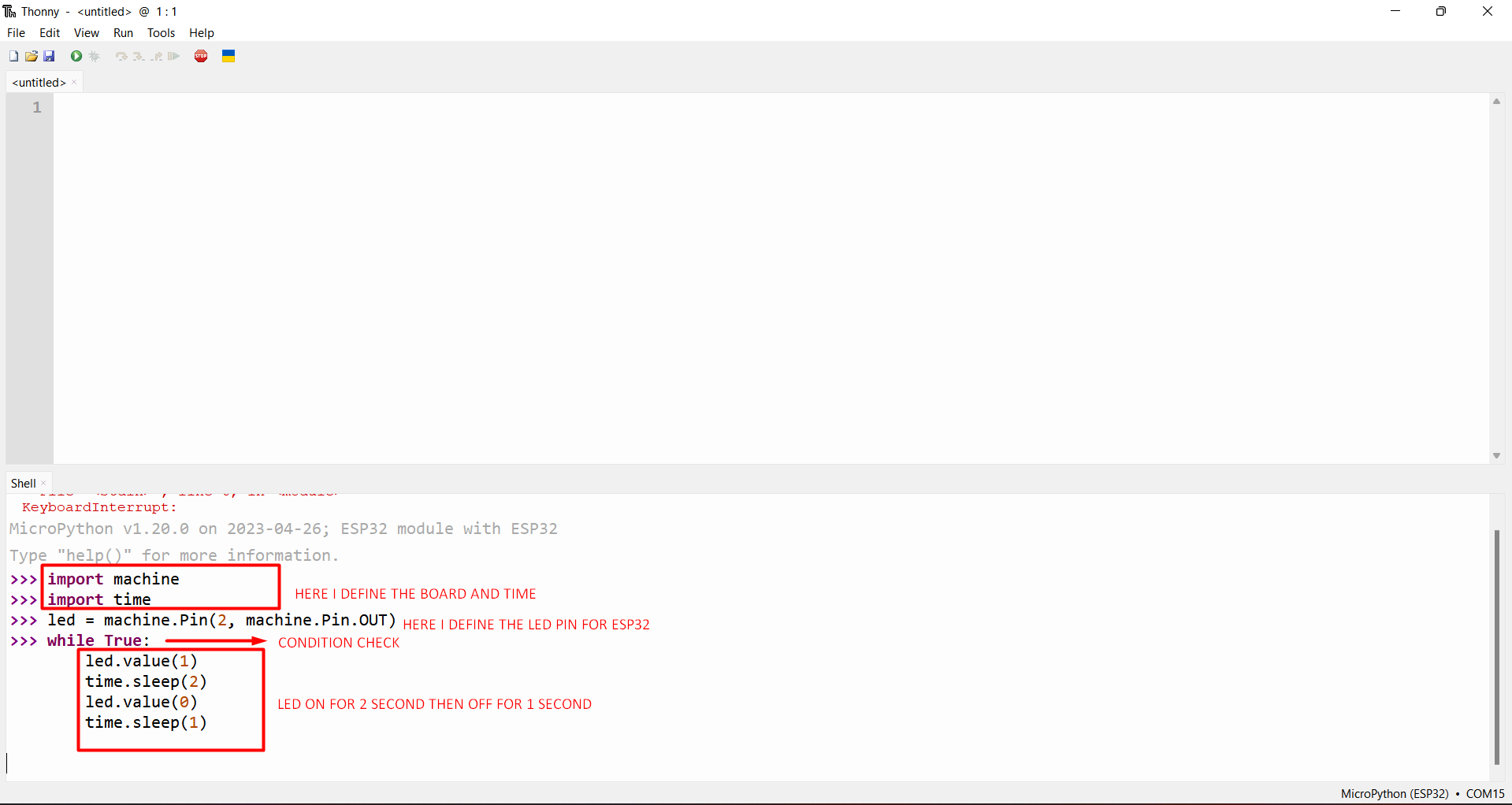
After that I learn the blink code in micropython. We know that there is inbuilt LED is present on the board, which connect to the pin no 2.
Then I firstly understand the blink code and then do some modification on it then click on enter. I making the Led on for 2 second and then off for
1 second.
Code Explaination
Result Video
Learning outcomes
-I learned about the Microcontrollers and their working.-I learned about the Esp 32 board and learned about how to add this board into arduino ide and upload code.
-I controlled the board by using blynk server via wifi.
-I also tried the micropython language for programming